Enrico Gullotti
earnest wonderer
earnest wonderer
IC.Shape 1.1
The Brush The brush is the master instrument of the IC.Shape script. It makes use of the The Painter Interface, a general API introduced in 3ds Max 5 which provides tools for painting on meshes. The script exploits its capabilities to manipulate elements and sculpt Editable Polys. Each tool has his own unique brush and keeps the properties set through different painting sessions.
The brush is made of three parts: Tip, Ring and Normal Vector, which could be set on the fly during the painting session.
Selection
Poly Model
Stack Status
Poly Properties
Display
Troubleshooting
Known Issues
 |
|
The Brush The brush is the master instrument of the IC.Shape script. It makes use of the The Painter Interface, a general API introduced in 3ds Max 5 which provides tools for painting on meshes. The script exploits its capabilities to manipulate elements and sculpt Editable Polys. Each tool has his own unique brush and keeps the properties set through different painting sessions.
The brush is made of three parts: Tip, Ring and Normal Vector, which could be set on the fly during the painting session.
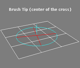 |
Brush Tip (center of the cross) It is the center of the cross formed by the two perpendicular diameters of the external ring. It is the point of maximum influence in painting and determines the brush position.
|
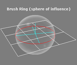 |
Brush Ring (sphere of influence) It is a visual representation of brush dimension. It is the equator of a sphere of influence centered in the brush tip.
|
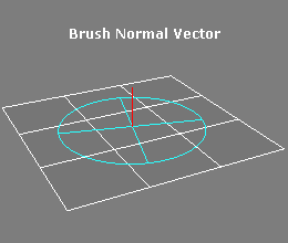 |
Brush Normal Vector
It is a visual representation of brush strength. This value ranges from 0 to 1, where 0 means no effect at all and 1 is the maximum. When a pressure sensitive device is used, and Disable Pressure setting is disabled, the effective influence multiplier is got by: Influence = Brush Strength * Pressure Strength
|
Selection
 |
|
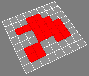
Vertex Sub-Object level  | ||||||||||
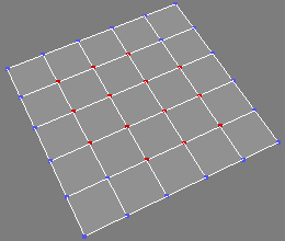
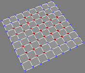
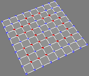
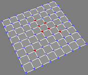
| Enables/Disables vertex sub-object editing. If CTRL is pressed before switching to this level from another, the actual selection is converted to a vertex selection.
|
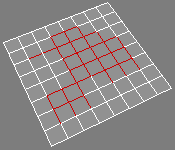
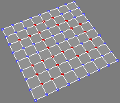
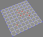
| Source Selection | Convert to Verts CTRL + Click |
Convert To Outer Verts SHIFT + Click |
Convert to Inner Verts CTRL + SHIFT + Click |
|
 |
 |
 |
 |
|
 |
 |
 |
 |
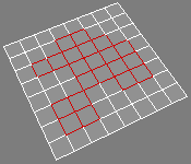
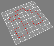
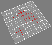
Edge Sub-Object level  | ||||||||||
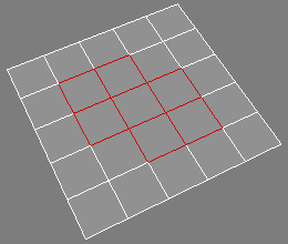
| Enables/Disables edge sub-object editing. If CTRL is pressed before switching to this level from another, the actual selection is converted to an edge selection.
|
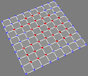
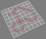
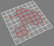
| Source Selection | Convert to Edges CTRL + Click |
Convert To Outer Edges SHIFT + Click |
Convert to Inner Edges CTRL + SHIFT + Click |
|
 |
 |
 |
 |
|
 |
 |
 |
 |
| Border Sub-Object level |
||||||
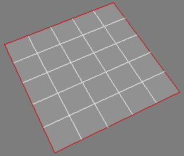 |
Enables/Disables border sub-object editing. If CTRL is pressed before switching to this level from another, the actual selection is converted to a border selection.
|
Polygon Sub-Object level  | ||||||||||
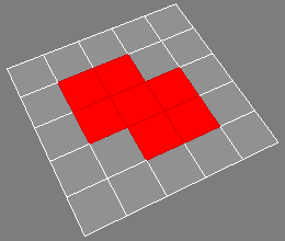
| Enables/Disables polygon sub-object editing. If CTRL is pressed before switching to this level from another, the actual selection is converted to a polygon selection.
|
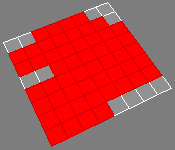
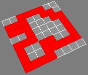
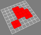
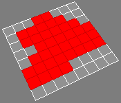
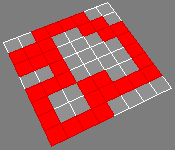
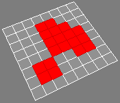
| Source Selection | Convert to Polys CTRL + Click |
Convert To Outer Polys SHIFT + Click |
Convert to Inner Polys CTRL + SHIFT + Click |
|
 |
 |
 |
 |
|
 |
 |
 |
 |
| Element Sub-Object level |
||||||
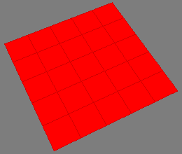 |
Enables/Disables element sub-object editing. If CTRL is pressed before switching to this level from another, the actual selection is converted to an element selection.
|
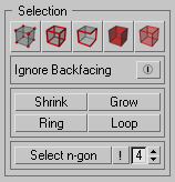
| Ignore Backfacing When active, Selection tools and Poly Model tools ignore active sub-objects whose normals point away from active viewport direction. It operates the standard Ignore Backfacing too. |
| Shrink Selection |
||
| Reduces the sub-object selection area by unselecting the outermost sub-objects. If the selection size can no longer be reduced, the remaining sub-objects are unselected. |
| Grow Selection |
||
| Expands the selection area outward in all available directions. For this function, a border is considered to be an edge selection. |
Select Ring  |
||
| Expands an edge selection by selecting all edges parallel to the selected edges. Select Ring applies to vertex, edge and In order to work in vertex and polygon sub-object editing mode, at least two contiguous elements must be selected. |
Select Loop  |
||
| Expands the selection as far as possible, in alignment with selected edges. Select Loop applies to vertex, edge and In order to work in vertex and polygon sub-object editing mode, at least two contiguous elements must be selected. |
| Select n-gon Selects all polygons matching chosen search criteria. Automatically switches to Polygon sub-object if polygons are found.
|
Poly Model
 |
|
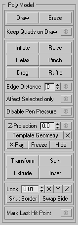
Draw Tool  Polygon drawing tool. When active, enables the drawing of new edges on the Editable Poly surface by connecting existent edges, or vertices. The Draw tool performs a wide number of different actions without any complex modifier keys combination. It recognizes the actual status and behaves accordingly. The use of a graphic tablet makes drawing more comfortable and accurate. Adjust the brush ring to meet each drawing task easily.
|
||||||||||
Draw [Left Mouse Button]  |
||||||||||
It is the basic use of the Draw tool, it feels like drawing lines on paper, with some additional precision and snapping features.
|
||||||||||
Draw Loop [SHIFT + Left Mouse Button] |
||||||||||
Create an Edge Loop by connecting all edges parallel to the one crossed by the brush tip.
|
||||||||||
Draw in the middle of edges [CTRL + Left Mouse Button] |
||||||||||
The brush behaves like in normal drawing, but creates vertices and edges snapping to the middle of edges crossed by the brush tip.
|
||||||||||
Create Polygons [ALT + Left Mouse Button]  |
||||||||||
| It is a useful feature when starting from a very simple base Editable Poly want to extend it to obtain a more complex model. It works by dragging the brush out of the Editable Poly. If the last element crossed is an edge, creates a polygon from it, otherwise creates a polygon from the last vertex crossed and contiguous edges. When creating polygons by border edge, the "auto-bridge" and "auto-weld" functions are active. The first bridges the dragged edges, while the second welds dragged vertices. The newly created polygon share the smoothing groups of the source and target polygons.
|
||||||||||
Erase Tool  Polygon erasing tool. When active enables the erasing of edges and vertices on the Editable Poly surface. The use of a graphic tablet makes erasing more comfortable and accurate. Adjust the brush ring to meet each erasing task easily.
|
||||||||||
Erase [Left Mouse Button]  |
||||||||||
It is the basic use of the Erase Tool, it feels like erasing lines on paper, with some additional precision and snapping features.
|
||||||||||
Erase Loop [SHIFT + Left Mouse Button] |
||||||||||
Removes the Edge Loop which comprises the edge crossed by the brush tip.
|
||||||||||
Collapse [CTRL + Left Mouse Button] |
||||||||||
Collapses groups of contiguous sub-objects by welding their vertices to a vertex at the selection center.
|
||||||||||
Delete Polygons [ALT + Left Mouse Button]  |
||||||||||
Pressing and keeping down the ALT button during the erasing session, disables the normal edge erasing and forces the sole removal of polygons from the perimeter of the mesh.
|
||||||||||
| Keep Quads on Draw |
||
| When active, prevents the formation of three- and five-sided polygon when cutting four-sided polygons (quads) by adding automatically the edge needed to create three quads. This feature is a bit less robust than the normal drawing mode, please use it with care (slower), and when needed only. |
| Inflate / Deflate |
||||||||
Deforms the Editable Poly surface in the direction of the normal vector of each vertex. Inflate Tool applies the shift in the positive direction of surface normal vectors, whereas Deflate Tool applies the shift in the negative direction of surface normal vectors. The calculation takes in account the deformation derived by the painting stroke in progress, therefore the practical effect is that of inflating / deflating the mesh.
|
| Raise / Lower |
||||||||
Deforms the Editable Poly surface in the direction of the normal vector of each vertex. Raise Tool applies the shift in the positive direction of surface normal vectors, whereas Lower Tool applies the shift in the negative direction of surface normal vectors. The calculation doesn't take in account the deformation derived by the painting stroke in progress, therefore the practical effect is that of raising / lowering the mesh.
|
| Relax / Stress |
||||||
Smooths the Editable Poly surface. Each vertex is shifted in the direction of the average position of the contiguous ones. Relax Tool applies the shift in the positive direction, whereas Stress Tool applies the shift in the negative direction.
|
| Pinch / Stretch |
||||||||
Deforms the surface
to gather or push away vertices from the tip of the brush. Each vertex is shifted in the direction of the position of the brush tip. Pinch Tool applies the shift in the positive direction, whereas Stretch Tool applies the shift in the negative direction.
|
| Drag / Smudge |
||||||||
Deforms the mesh by shifting the vertex in the direction of the brush stroke. Drag Tool behaves like a move vertex action of a soft selection, without the need of selecting anything, just point and drag. Brush dimension determines the outer limit of influence. Smudge Tool behaves like a magnet whose force is driven by brush strength. At maximum strength it is like the drag tool, while at lower values it allows softer mesh shifts.
|
| Ruffle / Flatten |
||||||||
Ruffle Tool deforms the mesh applying to each vertex a shift in a random direction from its original position. Flatten Tool shifts each vertex to a plane perpendicular to the normal vector of the surface in the point of the brush stroke. It causes the surface to average to a plane. It is more useful in combination with Affect Selected only, to limit its influence to the area to flatten.
|
| Edge Distance Limit |
||
| When active, restricts the area of influence of the active tool. It represents the maximum distance from the brush tip to the brush ring measured in edges to travel before brush strength is cut down to zero. |
| Affect Selected only |
||
| When active, restricts the area of influence of the active tool to the actual sub-object selection. When active, clicking out of the mesh with the brush tip of modeling polygons tools, doesn't deselect elements. When is activated, turns off Mark Last Hit Point, and vice versa. The tools affected by this setting are:
|
| Disable Input Device Pressure Effects |
||
| When active, disables the input device pressure effects, like a graphic tablet whose pressure is considered to be always at maximum value, therefore the brush is influenced by its strength value only.
This setting has no influence if no pressure sensitive device is used, like a standard mouse. The tools affected by this setting are:
For the Smudge brush the pressure sensitivity is always considered to be enabled. If the input device has no pressure sensitivity, it behaves like the Drag brush. |
||
 |
Z-Projection on a Template Geometry Z-Projection allows to use a scene Geometry Object as template for shaping the actual Editable Polygon. Every transformed sub-object element is instantly projected along the viewport Z-Axis on the active template geometry and remains stuck to it. Brushes that support this feature, like Drag Brush, project all their transformations on the template surface positive side, while all the others, like Inflate Brush, behave in the standard mode. A positive offset from the tempate geometry object can be set to prevent the loss of volume while rebuilding a low-poly surface from a high-poly template. Notes
|
|
The tools affected by this setting are:
|
||
| Shows the status of Z-Projection feature. The toggle on the right indicates whether or not the Z-Projection has to be used if available, it is freely checkable. The label on the left shows the availability status of the Z-Projection feature depending on various factors, like the selected Template Geometry, the selected Editable Poly to shape, the Brush actually active. The spinner sets the offset value to keep from the Template Geometry surface. |
||
| The Pickbutton on the left selects the Template Geometry, while the button on the right removes it. | ||
| The checkbuttons manage the visibility and selectability status of the Template Geometry. |
Transform  |
||||||||||||||
| Manages move and roto-scale transforms in screen coordinate space. This tools works in every sub-object level. If nothing is selected, the first stroke selects elements, the second stroke, if started over the selection or outside the object, leads to the shift, otherwise deselects elements and star a new selection process. Like in standard 3ds Max workflow, CRTL adds painted elements to selection and ALT removes painted elements from actual selection. SHIFT activates the roto-scale transform with center in the middle of selection.
|
| Spin Edge |
||||
Makes the edge shared by two polygons to spin, connecting next vertices of the polygon pair. It is not limited by the number vertices/edges of the adjacent polygons. Its use is alike the action of a finger pushing the edge. The half and the side where the edge is touched determines the spin direction.
|
Extrude  |
||||||||||||||
| Performs an extrusion of polygons by dragging them from the original position in screen coordinate space. If nothing is selected, the first stroke selects elements, the second stroke, if started over the selection or outside the object, leads to the extrusion, otherwise deselects elements and star a new selection process. Like in standard 3ds Max workflow, CRTL adds painted elements to selection and ALT removes painted elements from actual selection. SHIFT constraints the direction of the extrusion to the average of selection normals. Polygons created from Extrude share Smoothing Groups of their sources. Unlike 3ds Max standard extrusion tool, borders do not contribute to extruded mesh.
|
Inset  |
||||||||||||
| Performs an inset of polygons. If nothing is selected, the first stroke selects elements, the second stroke, if started over the selection or outside the object, leads to the inset, otherwise deselects elements and star a new selection process. Like in standard 3ds Max workflow, CRTL adds painted elements to selection and ALT removes painted elements from actual selection. Polygons created from inset share Smoothing Groups of their sources.
|
| Axis Lock |
||
Axis Lock setting preserves the mesh border laying on a cartesian plane passing through the worldspace origin. It can be activated for planes X = 0, Y = 0 and Z=0. If a border vertex position is within the threshold expressed by the spinner, cannot move along the axis locked, thus limiting its shift on the perpendicular cartesian plane. All the tools in the Poly Model section submit to these settings. More than one axis lock can be active at the same time. |
||
Shut Border |
||
Causes the border vertices laying on the cartesian plane selected by the Axis Lock, whose position is within the threshold expressed by the spinner, to move along that axis up to zero. Its practical effect is well expressed in conjunction with a Symmetry Modifier, to fix any mesh imprecision on the mirror plane that may arise during the modeling process. |
||
Swap Side |
||
Mirrors the model relative to the plane selected by the Axis Lock. Its practical effect is well expressed in conjunction with a Symmetry Modifier, being able to select which side of the mesh is more comfortable to model along the process. |
| Mark Last Hit Point |
||
|
|
When active, creates a very small three-sided polygon in the position of the last point where the brush touched the mesh, and selects it. This feature is useful for viewport navigation: if standard 3ds Max "Arc Rotate SubObject" mode is active, the perspective as well as parallel view will orbit around the last touched point, avoiding the loose of focus on the modeling position. When is activated, turns off Affect Selected only, and vice versa. The accessory three-sided polygon is automatically deleted:
|
Stack Status
 |
|
 |
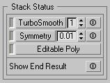
Stack controls Stack controls section provides an easy interface to manage the Modifier Stack by activating and deactivating fundamental modifiers and changing some of their parameters on the fly without the needing for the full Modify Panel. Its buttons represent the Base Object (Editable Poly), the Symmetry Modifier(s) for symmetrical models, and the TurboSmooth Modifier(s). The left indicator tells what's the actual object in the Modifier Stack:
The state (enabled or disabled) "power" button on the right of modifiers buttons tells whether there are such objects in the active selection Modifiers Stack.
By clicking the buttons with modifier names, activates the corresponding object in the stack. If there is more than one object of the same kind, like two Symmetry modifiers, or two TurboSmooth modifiers, the first found from the actual position will become active, going from bottom to top of the stack. Every subsequent click will activate next modifier of the same kind. If the top of the stack is reached, the first object of the selected type found after the base object will be activated. If there's not a modifier of the selected kind in the stack, a popup will prompt asking if it should be added in the actual selected object Modifier Stack. Symmetry will be added after the base object, while TurboSmooth will be added on top of the Stack. By clicking the "power" button on the right of modifiers activators, all the object of that kind present in the actual Modifier Stack will be turned off if on, and on if off. TurboSmooth
Symmetry
Editable Poly
|
| Show End Result Toggles the state of Modify Panel "Show End Result" button. It shows the selected object as it will appear after all modifications in the stack have taken place, regardless of current position in the stack. When this toggle is turned off, the object appears as modified up to the current modifier in the stack. |
Poly Properties
 |
|
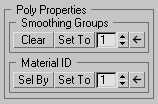
| Smoothing Groups Smoothing Groups section provides a compact interface for basic functions.
|
| Material ID Material ID section provides a compact interface for basic functions.
|
Display
|
| Hide / Unhide / Invert |
||
| Hides, unhides or inverts visibility of selected sub-objects. |
Troubleshooting
- The program seems to hang and activating tools has no effect. 3ds Max Painter Inteface hasn't ended a painting session and cannot start a new one. You need to do it by script:
- Go to MAXScript Mini Listener, the white textfield bottom left.
- Type: thePainterInterface.endPaintSession();
- Press Enter and try to use the tools again.
- The 3ds Max undo system doesn't work anymore. Sometimes it happens that the undo stack doesn't record actions performed. This doesn't appear to be connected with the script. There isn't solution other than closing and starting again 3ds Max. Please remember to save often.
Known Issues
- IC.Shape is based on the same 3ds Max API employed in example by the Skin Modifier. Please never use IC.Shape with such modifiers active in the Editable Poly Modifier Stack.